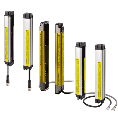
F3SJ
Offering the best selection of safety light curtains for your guarding needs.
Omron's F3SJ series of safety light curtains offer a tailored approach for a variety of production environments. Conventional safety light curtains offer full-featured models, even when only simple intrusion detection is needed. The F3SJ series offers a product range that allows you to choose the best product according to your application needs. The F3SJ series now allows you to select the best safety light curtain for your application environment without paying for unused functions.
Three F3SJ types allow easy selection for your application.
The EASY type (F3SJ-E)
- For simple and affordable hand protection
- Easy to install
- Mounting now takes less than half the man-hours that conventional models take.
- For simple hand protection, series connection and muting functions
- The muting function allows use of the safety light curtain in a variety of manufacturing environments.
- The flexible mounting supports up to three sets of series-connected sensors.
- For finger protection and series connection
- The detection capability supports finger protection through use of 14mm resolution
- Has a wide variety of muting and blanking functions to increase productivity.
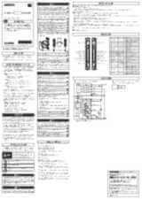
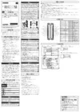
Specifications & ordering info
Ordering information

Safety light curtain model list
F3SJ-A14 series (9 mm gap), F3SJ-A14 TS series (9 mm gap)
|
Protective height (mm)1 |
||
|---|---|---|
F3SJ-A30 series (25 mm gap)
|
Protective height (mm)2 |
||
|---|---|---|
Accessories (sold separately)
Single-end connector cable (2 cables per set, for emitter and receiver)
For wiring with safety circuit such as single safety relay, safety relay unit, and safety controller.

|
|||
Setting Tools

|
Connector cap (1), |
Sensor Mounting Brackets (Sold separately)


Laser pointer

|
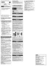
Specifications
F3SJ-A ____ P14/P30
Response Time
Note: Use the following expressions for series connection.
-
•
For 2-set series connection:
Response time (ON to OFF): Response time of the 1st unit + Response time of the 2nd unit - 1 (ms), Response time (OFF to ON): Response time calculated by the above × 4 (ms) -
•
For 3-set series connection:
Response time (ON to OFF):
Response time of the 1st unit + Response time of the 2nd unit + Response time of 3rd unit - 5 (ms), Response time (OFF to ON): Response time calculated by the above × 5 (ms)
For models with the “-TS” suffix, multiply the response time obtained by the above × 5 (ms), or use 200 ms, whichever is less.) -
•
For 4-set series connection:
Response time (ON to OFF): Response time of the 1st unit + Response time of the 2nd unit + Response time of the 3rd unit + Response time of the 4th unit - 8 (ms)
Response time (OFF to ON): Response time calculated by the above × 5 (ms)
Cable extension length
Total cable extension length must be no greater than the lengths described below.
When the F3SJ and an external power supply are directly connected, or when the F3SJ is connected to a G9SA-300-SC.
|
Using incandescent lamp for auxiliary output and external indicator output |
||||
When connected to the F3SP-B1P
Note: Keep the cable length within the rated length. Failure to do so is dangerous as it may prevent safety functions from operating normally.
Connections
Basic Wiring Diagram
PNP Output
Wiring when using manual reset mode, external device monitoring.

Need assistance?
We’re here to help! Reach out, and our specialists will assist you in finding the best solution for your business.
Kontakta mig F3SJ
Tack för din förfrågan. Vi återkommer inom kort.
Vi har tekniska problem. Din formulär har inte varit framgångsrik. Vi ber om ursäkt och försök igen senare.
Offert för F3SJ
Fyll i alla obligatoriska fält. Vänligen fyll i alla fält markerade med *. Dina personliga uppgifter behandlas konfidentiellt.
Tack för din offertförfrågan. Vi återkommer med önskad information inom kort.
Vi har tekniska problem. Din formulär har inte varit framgångsrik. Vi ber om ursäkt och försök igen senare.
Downloads