GI-S Series
GI-S Series
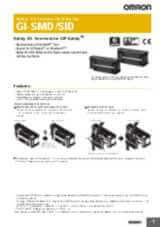
Safety I/O Terminals for CIP Safety™
- Safety Remote Digital Blocs
- Individual Test Pulses for better diagnostics
- CIP-Safety on EtherNet/IP is Supported
- Standard-feature EtherNet/IP Communications Port
- Separate Power supply for Logic and S-I/O's
- Can work as remote Safety I/O's in combination with NX-SL5000 series with NX-CSG320 or NX102 using port 2 A/B
Specifications & ordering info
Ordering information
| Specifications | I/O capacity | Unit version | Order code | ||||
|---|---|---|---|---|---|---|---|
| Communication protocol | Number of connectors | Number of networks | Safety inputs | Pulse outputs | Safety outputs (for PNP) |
||
| EtherNet/IP | 2 | 1
2
PORT1 and PORT2 are ports
with switching hub. |
12 inputs | 12 outputs | 4 outputs | Ver. 1.2 | GI-SMD1624 |
| – | GI-SID1224 | ||||||
Specifications
Regulations and Standards
GI-S-series safety I/O terminals
| Certification body | Standards |
|---|---|
| TÜV Rheinland | EN ISO 13849-1IEC 61508 parts 1-7IEC/EN 62061IEC/EN 61131-2 |
| UL | NRAQ (UL61010-1, and UL 61010-2-201)NRAG (UL 121201)NRAQ7 (CSA C22.2 No. 61010-1, and CSA C22.2 No. 61010-2-201) |
The FSoE protocol was certified for applications in which OMRON FSoE devices are connected to each other. For compatibility with FSoE devices other than OMRON FSoE devices, the customer must validate FSoE communications.
By using GI-S-series safety I/O terminals, you can build a safety control system that meets the followings.- Requirements for SIL 3 (Safety Integrity Level 3) in IEC 61508, IEC/EN 62061, (Functional Safety of Electrical/Electronic/Programmable Electronic Safety-related Systems)
- Requirements for PLe (Performance Level e) and for safety category 4 in EN ISO13849-1
Also, GI-S-series safety I/O terminals have been registered for conformity to RCM, EAC, and KC (Korean radio regulation).
General Specifications
| Item | Specifications | |
|---|---|---|
| Enclosure | Mounted in a panel (open type) | |
| Operating environment | Ambient operating temperature | 0 to 55°C |
| Ambient operating humidity | 10% to 95% (with no condensation or icing) | |
| Atmosphere | Must be free from corrosive gases | |
| Ambient storage temperature | −25 to 70°C (with no condensation or icing) | |
| Altitude | 2,000 m max. | |
| Pollution degree | 2 | |
| Insulation class | CLASS III (SELV) | |
| Overvoltage category | II | |
| EMC immunity level | Zone B: IEC 61131-2 | |
| Vibration resistance | Conforms to IEC 60068-2-6 5 to 8.4 Hz with amplitude of 3.5 mm 8.4 to 150 Hz, acceleration of 9.8 m/s2 100 min. in each X, Y, and Z directions (10 sweeps of 10 min. each = 100 min. total) |
|
| Shock resistance | Conforms to IEC 60068-2-27 147 m/s2 3 times in each X, Y, and Z directions |
|
| Insulation resistance | 20 MΩ between isolated circuits (at 100 VDC) | |
| Dielectric strength | 500 VAC between isolated circuits for 1 minute at a leakage current of 10 mA max. | |
| Installation method | DIN Track mounting (IEC 60715 TH35-7.5/TH35-15) | |
| Degree of protection | IP20 | |
GI-SMD1624/GI-SID1224
| Model | GI-SMD1624 | GI-SID1224 | |
|---|---|---|---|
| Number of safety input points | 12 | ||
| Number of safety output points | 4 | – | |
| Number of test output points | 12 | ||
| OMRON special
safety input device
2
OMRON special safety input devices are the following input devices: - Safety mat UMA/UM - Safety edge SGE - Single-beam safety sensor E3ZS - Non-contact door switch D40A/D40Z |
Connection unavailable | ||
| LED indication | [V0] LED, [IN [OUT [PORT |
[V0] LED, [IN [V1] LED, [MS] LED, [NS] LED, [PORT |
|
| Hardware switch setting |
[IP ADDRESS] switch x3 (MODE, x16, x1)  Factory default Factory defaultGI-SMD1624: 192.168.250.2 [IP ADDRESS] Switch= “002” GI-SID1224: 192.168.250.3 [IP ADDRESS] Switch= “003“ |
||
| Safety input type | IEC61131-2 type3 PNP (sinking inputs) | ||
| Safety input current | 6 mA max. | ||
| Safety input ON voltage | 11 VDC min. | ||
| Safety input OFF voltage/OFF current | 5 VDC max./1 mA max. | ||
| Safety output type | Source output (for PNP) | ||
| Safety output rated current | 0.5 A max. |
2
GI-SID1224
has no output signal terminal and no output power supply is connected. |
|
| Maximum total safety output current | 2.0 A | ||
| Safety output ON residual voltage | 1.2 V max. (between V1 and each output terminal) |
||
| Safety output OFF residual voltage | 2.0 V max. (between G1 and each output terminal) |
||
| Safety output leakage current | 0.1 mA max. | ||
| Test output type | Source output (for PNP) | ||
| Test output rated current | 0.7 A max. | ||
| Maximum total test output current | 5.0 A | ||
| Test output ON residual voltage | 1.2 V max. (between V0 and each output terminal) | ||
| Test output leakage current | 0.1 mA max. | ||
| External
dimensions
2
Projections are not included. |
170 (W) x 65 (H) x 55 (D) | ||
| Weight | 400 g | ||
| Number of communications that can be set between NX Units |
254 ports max.
2
Projections are not included. |
||
| Unit power supplies |
Power supply voltage | 24 VDC (20.4 to 28.8 VDC) | |
| Current consumption
2
Inrush
current when the supply power is turned ON from the static power-OFF
state. Inrush current value may vary depending on conditions. For
your selection of fuses, breakers, and external power supply units,
take into account the conditions to be used to select those that
have a margin in characteristics and capacity. |
250 A max. | ||
| Inrush current | On cold start at normal temperature50 A max., 0.1 ms max. | ||
| Power supply terminal current carrying capacity
2
Current-carrying capacity allowed to continuously flow through the terminal. This current must not be exceeded in case crossover wiring is done for the unit power supply. |
5 A | ||
| Insulation type | No insulation: Between unit power supply terminal and internal circuit | ||
| Output power supply |
Power supply voltage | 24 VDC (20.4 to 28.8 VDC) |
2 GI-SID1224
has no output signal terminal and no output power supply is connected. |
| Current consumption | 50 A max. | ||
| Inrush current | On cold start at normal temperature 50 A max., 0.1 ms max. |
||
| Power supply terminal current carrying capacity
2
Current-carrying capacity allowed to continuously flow through the terminal. This current must not be exceeded in case crossover wiring is done for the unit power supply. |
5 A | ||
| Insulation type | Photocoupler insulation | ||
| External connection terminal |
Communication connector | EtherNet/IP communication RJ45 x 2 | |
| Screwless clamp terminal block |
Top terminal block
Bottom terminal block
|
Top terminal block
Bottom terminal block
|
|
| Inter-terminal connection diagram |
V0/G0 Unit power supply |  |
|
| V1/G1 Output power supply |  |
2 GI-SID1224
has no output signal terminal and no output power supply is connected. |
|
| Installation direction and restriction | No restriction | ||
| Protective function | Overvoltage protection, overcurrent protection | ||
Built-in EtherNet/IP port specifications
This section describes the field bus specifications of the safety I/O terminal.
| Item | Specifications | |
|---|---|---|
| GI-SMD1624 / GI-SID1224 | ||
| Communications protocol | TCP/IP, UDP/IP | |
| Support services | Sysmac Studio connection, CIP message communication, DHCP (client) | |
| Number of logical ports | 2 | |
| Physical layer | 100BASE-TX | |
| Transmission specifications | Media access method | CSMA/CD |
| Modulation | Baseband | |
| Transmission path | Star, daisy chain, mixed (star and daisy chain) | |
| Transmission rate | 100M bit/s (100BASE-TX) | |
| Transmission media | Twisted-pair cable (shielded: STP): category 5/5e or higher | |
| Transmission distance | 100 m max. (distance between hub and node) | |
| Number of daisy chain connections | 8 units | |
| CIP messaging service: Explicit message UCMM (non-connection type) |
Maximum number of clients that can communicate simultaneously: 8/Logical ports | |
| Implicit (I/O) connection | Exclusive Owner (EO) connection | 1 |
| EtherNet/IP conformance test | CT9 compliant | |
| Ethernet interface |
100BASE-TX Auto Negotiation Auto-MDI |
|
Version Information
This section describes the combinations that can be used of the unit versions of the Safety CPU Unit and the Communication Control Unit, Machine Automation Controller, and the version of the Sysmac Studio.
| Safety I/O terminal | Corresponding unit version/version | ||||
|---|---|---|---|---|---|
| Model | Unit version |
Safety CPU Unit NX-SL5700NX-SL5500 |
Communication Control Unit NX-CSG320 |
Machine Automation Controller NX102- |
Sysmac Studio |
| GI-SMD1624 | Ver. 1.2 | Ver. 1.3 | Ver. 1.01 | Ver. 1.31 | Ver. 1.24 |
| GI-SID1224 | Ver. 1.2 | Ver. 1.3 | Ver. 1.01 | Ver. 1.31 | Ver. 1.24 |
Need assistance?
We’re here to help! Reach out, and our specialists will assist you in finding the best solution for your business.
Kontakta mig GI-S Series
Tack för din förfrågan. Vi återkommer inom kort.
Vi har tekniska problem. Din formulär har inte varit framgångsrik. Vi ber om ursäkt och försök igen senare.
Offert för GI-S Series
Fyll i alla obligatoriska fält. Vänligen fyll i alla fält markerade med *. Dina personliga uppgifter behandlas konfidentiellt.
Tack för din offertförfrågan. Vi återkommer med önskad information inom kort.
Vi har tekniska problem. Din formulär har inte varit framgångsrik. Vi ber om ursäkt och försök igen senare.
Relaterade produkter

Downloads
_instruction_manual_en.jpg)