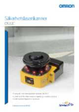
OS32C
Safety laser scanner
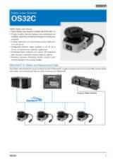
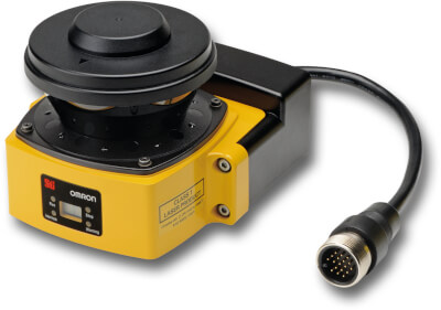
Small size, less weight and low-power consumption are extending operation time of battery powered systems like automated guided vehicles (AGVs). Safety laser scanner OS32C covers all these requirements in collision avoidance, presence and intrusion detection applications. Maintenance is made simple since diagnosis is clear having LED displays.
- Type 3 Safety Laser Scanner complies with IEC61496-1/-3
- 70 sets of safety zone and warning zone combinations
- Safety zone up to 4m and warning zone(s) up to 15m.
- 8 Individual Sector indicators and various LED for clear status indication
- Reference boundary function prevents unauthorized change of scanner position
Specifications & ordering info
| Produkt | Type of safety according to IEC 61496-1 | Maximum safety range | Maximum warning range | Communication port(s) | Cable entry direction | Type of switching output of the OSSD | Key features | Connection method | Description | |
|---|---|---|---|---|---|---|---|---|---|---|
|
|
3 | 3 m | 10 m | Back | PNP | Configurable object resolution of 30, 40, 50 or 70 mm, Manual/auto start, Reference boundary monitoring | Pigtail connector | Safety laser scanner, OS32C, safety radius 3 m, warning zone 10 m, PLd & Cat 3 (ISO 13849-1) , 24 VDC, back location cable exit |
|
|
|
|
3 | 4 m | 15 m | Back | PNP | Configurable object resolution of 30, 40, 50 or 70 mm, Manual/auto start, Reference boundary monitoring | Pigtail connector | Safety laser scanner, OS32C, safety radius 4 m, warning zone 15 m, PLd & Cat 3, 24 VDC, back location cable exit |
|
|
|
|
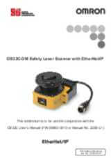
3 | 3 m | 10 m | EtherNet/IP | Back | PNP | Configurable object resolution of 30, 40, 50 or 70 mm, Manual/auto start, Reference boundary monitoring | Pigtail connector | Safety laser scanner, measurement and EtherNet/IP, OS32C, safety radius 3 m, warning zone 10 m, PLd & Cat 3 (ISO 13849-1), Ethernet, 24 VDC, back location cable exit |
|
|
|
3 | 4 m | 15 m | EtherNet/IP | Back | PNP | Configurable object resolution of 30, 40, 50 or 70 mm, Manual/auto start, Reference boundary monitoring | Pigtail connector | Safety laser scanner with measurement data, OS32C, safety radius 4m, warning zone 15 m, PLd & Cat 3, EtherNet/IP, 24 VDC, back location cable exit |
|
|
|
3 | 3 m | 10 m | Side | PNP | Configurable object resolution of 30, 40, 50 or 70 mm, Manual/auto start, Reference boundary monitoring | Pigtail connector | Safety laser scanner, safety radius 3 m, warning zone 10 m, PLd & Cat 3 (ISO 13849-1), Ethernet, 24 VDC, side location cable exit |
|
|
|
|
3 | 4 m | 15 m | Side | PNP | Configurable object resolution of 30, 40, 50 or 70 mm, Manual/auto start, Reference boundary monitoring | Pigtail connector | Safety laser scanner, safety radius 4m, warning zone 15 m, PLd & Cat 3, 24 VDC, side location cable exit |
|
|
|
|
3 | 3 m | 10 m | EtherNet/IP | Side | PNP | Configurable object resolution of 30, 40, 50 or 70 mm, Manual/auto start, Reference boundary monitoring | Pigtail connector | Safety laser scanner, measurement and EtherNet/IP, safety radius 3 m, warning zone 10 m, PLd & Cat 3 (ISO 13849-1), Ethernet, 24 VDC, side location cable exit |
|
|
|
3 | 4 m | 15 m | EtherNet/IP | Side | PNP | Configurable object resolution of 30, 40, 50 or 70 mm, Manual/auto start, Reference boundary monitoring | Pigtail connector | Safety laser scanner with measurement data, safety radius 4m, warning zone 15 m, PLd & Cat 3, EtherNet/IP, 24 VDC, side location cable exit |
|
Need assistance?
We’re here to help! Reach out, and our specialists will assist you in finding the best solution for your business.
Kontakta mig OS32C
Tack för din förfrågan. Vi återkommer inom kort.
Vi har tekniska problem. Din formulär har inte varit framgångsrik. Vi ber om ursäkt och försök igen senare.
Offert för OS32C
Fyll i alla obligatoriska fält. Vänligen fyll i alla fält markerade med *. Dina personliga uppgifter behandlas konfidentiellt.
Tack för din offertförfrågan. Vi återkommer med önskad information inom kort.
Vi har tekniska problem. Din formulär har inte varit framgångsrik. Vi ber om ursäkt och försök igen senare.
Downloads